
How can we help you today?
Solar cabling for commercial ground mount systems, Part 3
DC solar cable, some more ground mount action!
We continue on from part 2 in this solar cable for a 1 MW ground mount system series. Parallel strings, voltage drop considerations and allowing for errors when calculating your runs are all examined.
We now drill down into the details but first a recap from part 1 and 2.
Recap
The assumptions:
- Using 400 watt panels
- 1690 mm long and 1046 mm wide
- Configured in Portrait
- 2 x tiers
In addition looking at:
- 20 x panels per string
- Gap between tiers is 25 mm
- Gap between panels is 25 mm
- No parallel strings
- Inverters all on back of last row
- All DC runs from middle of the row to middle of last row
Panel layout


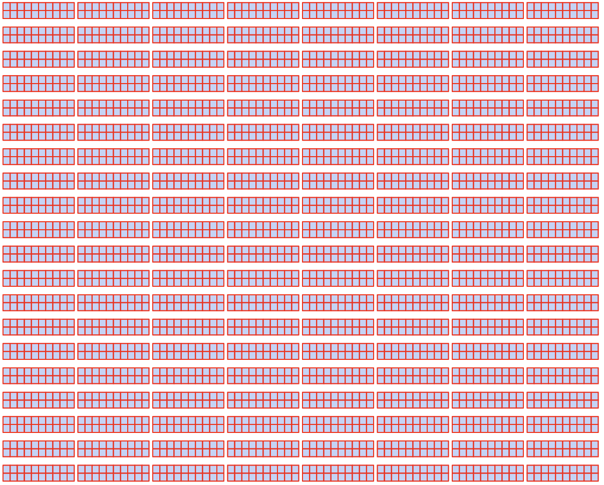
Per row there are 8 x strings of 20 x 400 watt panels per string so row length is approximately 85 metres wide.
There are 20 rows, total distance, North South with spacing is 142 metres which includes the 4 metre North and 4 metre South perimeter roads.

Distance from row 1 to row 20 is approximately 133 metres ( excluding perimeter access roads North South, 4 metres each)
- There is 160 strings, no parallel strings
- A lot of cable, in fact over 27,000 metres
- Each row requires 256 metres of DC cable
- And then there is the runs to the inverter station which is located behind row 20
The longest run, no parallel strings, using 4 mm2, just under 3% Vdrop.
The longest run, two strings paralleled, need to use 6 mm2 and the Vdrop is well under 3%
Also could use 4 mm2 possibly on the internal cable runs, within the string if combined Vdrop is less than 3%.

Questions to ask
We have made calculations in regards to 6 mm2 paralleling cables for the 1.28 MW project and have assumed the following:
- Internal cabling is all 6 mm2
- All the final runs from the centre of each row are in 6 mm2
- Volt drop and current carrying capacity of the 6 mm2 cable is satisfied

More questions to ask

Can I use 4mm2 within the rows on some rows that are closer to the end?
What are the dangers of using 2 x different cables within the same row, i.e. Use 4 mm2 from string to isolator and then 6 mm2 to inverter station?
At what point can I change to a 4 mm2 cable for the final run to the inverter station?
4 mm2, all individual strings, no parallel strings

Highest Vdrop Row 1: 2.33% for 166 m run
Lowest Vdrop Row 20: 0.46% for 33 m run
Average Vdrop is: 1.33%
6 mm2, all parallel strings
By paralleling and using 6 mm2 still under the 3% recommended voltage drop:
- Highest Vdrop Row 1: 2.80% for 166 metre run
- Lowest Vdrop Row 20: 0.31% for 33 metre run
- Average Vdrop is: 1.49%
6 mm2 and 4 mm2, all parallel strings
- Highest Vdrop Row 1: 2.80% for 166 metre run
- Lowest Vdrop Row 20: 0.46% for 33 metre run
- Average Vdrop is: 1.82%
Achieved using 6mm2 for the first 7 x rows but next 13 rows using 4 mm2

Cable details

Are further savings possible?
Could use a combo of 4 and 6 mm2 on individual rows For what additional financial benefit and could be confusing for the installers.
Conclusion
Your design needs to take into consideration the different cable characteristics and voltage drop and current carrying capacity of the cables has to be considered. Significant savings can be made if using parallel strings. Have to remember that as well as the costs of the materials the cost of installation has to be taken into consideration as well.
If you’d like to see more of what Greenwood Solutions get up to in the real world of renewable energy, solar, battery storage and grid protection check out the following pages:
https://www.greenwoodsolutions.com.au/industry
https://www.greenwoodsolutions.com.au/commercial
https://www.greenwoodsolutions.com.au/commercial/customer-stories
https://www.greenwoodsolutions.com.au/news

About the author
Veli Markovic
CEC Designer
Training videos
Every week we publish new videos and walkthroughs online.


